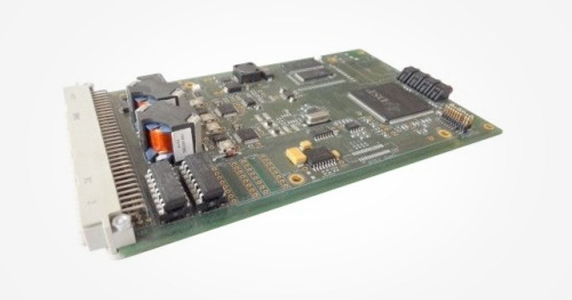
ModemB is a stand-alone DSP board with 2 analog input channels (from 10kHz to 150kHz), a RS485 serial link, 16 configurable digital inputs/outputs and one analog output. This electronic board is used in the station of Paris metro line #13 as a demodulator for the magnetic coupling communication with trains, to control the platform screen doors. ModemB is suitable for all applications requiring the computing power of a DSP and involving analog signals in the chosen frequency range (from 10kHz to 150kHz).
Used today for: railway Paris metro line #13 demodulation
Download datasheet
Project context
In the context of the installation of platform screen doors in some lines, the Paris metro company RATP needed on-board / wayside communication systems with safety critical transmission ranges. CLEARSY has studied, developed and installed such communication systems for lines #1 and #13, using the magnetic coupling principle which allows a guaranteed transmission range, impossible otherwise.
The magnetic coupling transmissions require specific modulation / demodulation techniques. The electronic board “ModemB” developed by CLEARSY provides the necessary computing power for such robust modulation / demodulation algorithms, suitable for the railway environment with high perturbation levels. In the 13 stations of the Paris metro line #13 that are fitted with platform screen doors, the platform doors open and close thanks to orders from the trains transmitted using ModemB (2 ModemB boards per station).
The ModemB electronic board is designed to be suitable for any autonomous modulation / demodulation application requiring high computing power, or more generally for all similar applications.
ModemB is equipped with carefully chosen components to match the widest application needs (see our datasheet below).
ModemBhas been produced in small amounts to equip stations in Paris metro line #13.
- Availability of a sample board for testing (loaded with the sample program)
- Board production : costs, possibilities, volumes
- Services: software development for ModemB
Short datasheet
- Processor: floating point DSP Texas Instruments TMS320C6713B, 200MHz
- 1600/1200 MIPS/MFLOPS
- Internal Memory/cache : 264Ko
- SDRAM 32Mo
- Flash (Application program) 4Mo
- 2 analog input channels, filtered and isolated
- Inputs via on-chip transformers (RM8 core, ratio to be adapted), with symmetrical inversed second stages (noise cancellation)
- Amplification / filtering using operational amplifiers (gain 0 to 2)
- 2 analog to digital converters TI ADS1601 16-Bit 1.25MSPS
- Input signals 10kHz to 150kHz, range -1.5v +1.5v
- 1 amplified analog output
- Digital to analog converterDAC8830
- Up to 8v, 23mA, from 10kHz to 150kHz
- 1 embedded SD card reader
- 1 serial link RS422/RS485 up to 115200 bauds
- 16 configurable digital inputs/outputs
- Each one of the 16 channels can be configured as input or output separatedly
- Maximum 3.3Vpp / 30kHz (input or output)
- 16 optocouplers for inputs
- 4 state LEDs controlled by program (front panel)
- 2 LEDs for liveliness (on board)
- Connectors: back connector male DIN 41612 96 contacts, JTAG connector 7×2 j20 male
- Size 100x160mm 3U
- Power supply 9 to 25v DC
- Testedfor climatic / vibrations / EMCaccording to French railways standards (wayside equipment).
- Programming : PC tools TI eXpressDSP (Code Composer Studio), real-time debug via JTAG (using Spectrum Digital XDS510 probe), SDS Flashburn for flash programming
- Sample program delivered: test program using all functionalities (converting analog signals received on 2 input channels into RS485 messages, digital output control). Applications programs may be derived from this sample.
Our actions
Expertise on M-FSK and M-PSK data transmission
- Study of the performances of demodulation
- Matlab simulation
- Measurements of sounds and electrical disturbances
- Modulation/demodulation algorithms
Software development
- DSP/BIOS coding in C and ASM
- Modulation/demodulation algorithms
Hardware development
- Electronic study & diagrams
- Placing & Routing, Manufacture
Lab and ground tests and measurements
- Sound tests
- Limitation tests
Link to this référence